
Unregulated Power Supply Tutorial
Intro
Hey! Why is my 9V wall-wart outputting 14V?!
We have written this tutorial to show you the innards of a wall-wart and explain why you can sometimes measure a higher voltage than what is specified on the label of your wall-wart.

On an unregulated power supply, wall wart, AC adapter, power brick, or whatever you want to call it, you usually see two specifications:
INPUT: AC 120V 60Hz 6W
OUTPUT: DC 6V 300mA
The input spec is straight forward as long as you are in the US using power from a regular wall outlet. What about the output?
If you measure the open circuit output with a multimeter on a device that specs the output as shown above, what do you think you should get?
Dumb Answer: about 6V and at least 300mA. Right?......WRONG!
Actually, you will often get a much higher voltage. The higher voltage can wreak havoc with your system if you are not planning for it. This behavior from an unregulated supply is normal and in this tutorial you will find out why the output spec is no where near the actual open circuit output. In addition, I will show how unregulated the supply really is. The output says DC, but in some circumstances, the output can be far from pure DC.
Guts of the Unregulated Power Supply
Lets first look at the internals of an unregulated power supply. Now, I am not going to go over the functionality in detail of each component, there are a bunch of resources on the web that go over how these things work. Here is the schematic and a quick rundown of components you might find:
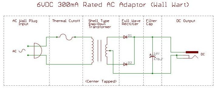
This is the schematic for the power supply I took apart. On the left is where you plug the unit into the wall and on the right is where you plug the unit into your system power input.

The wall outlet's AC signal will first see a thermal cutoff IC used to protect the supply if there is a large load attached that draws too much current. This is a nice added level of protection that is not found in all wall-warts, just the nice ones.

Next, you have a single phase, shell-type split-bobbin (shell bobbin), step-down transformer. Notice the coil of wire in the primary coil is thinner and contains more turns than the secondary coil (step down transformer).

A full wave center tapped rectifier using two diodes. The supply also has mounting holes in the PCB for what seems to be a bridge rectifier for higher output voltages using the same transformer. In addition, there is a simple filter capacitor to smooth the rectified signal.
Why do you get 10 Volts on a 6VDC supply?
In short, when you measure the open circuit voltage of this example 6V wall wart, you get about 10V. In this situation, there is very little current flowing through the power supply's secondary coil and thus not much of a voltage drop. When a load or your circuit is attached to the output of the supply, there is a voltage drop. The transformer will have a voltage drop from the open circuit 10V, according to Ohm's Law.
In a more detailed approach, the power supply will ideally have a Thevenin equivalent circuit (a voltage source and some overall resistance), which is attached to a load resistor that causes a voltage drop. Here is ideally what the circuit looks like with a load attached:

From this you get an KVL loop of:
VLoad = V0 – (ILoad*R0)
V0 is constant, as there is a specific voltage induced by the transformer. However, the load current is not constant.
An open circuit (no load) measurement has very little current flowing and the power supply inherently has a small resistance (about 4 Ohms), so the load current, ILoad, multiplied with the Thevenin resistance, R0, is close to zero and the load voltage is nearly equivalent to the Thevenin voltage, V0. You get about 10V from the above equation.
Let say you short circuit the power supply or use a very small resistance load, a bunch of current will now flow through the circuit. From the above equation, there will be a significant voltage drop detected on the load voltage.
Here is a chart of varying loads on our 6V/300mA example wall wart and their measured peak voltage, peak current, peak to peak ripple, and percentage of ripple in each output (you can ignore the ripple, for now):
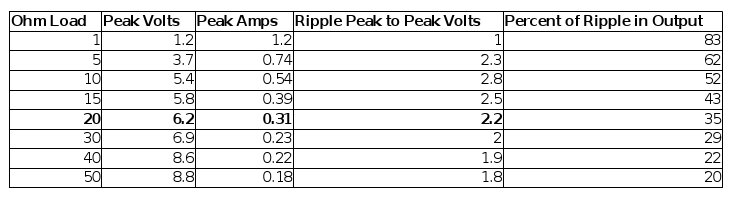
At small loads (large resistances), there is not a substantial voltage drop, because there is not much current flowing.
At a very large load (small resistance), there is a bunch of current flowing and a significant voltage drop. Also, the power supply is running way past its rated limit when the load is below 20 Ohms and the box that plugs into the wall will begin to heat up. At a certain point, the thermal cut off will break the connection in the primary coil and not until the box cools will the thermal cut off allow current to pass.
But I haven't actually addressed why the voltage drops and what are the mechanisms that cause the voltage drop?
In the above equation, if you substitute the numbers for the power supply in regulation (with a 20 ohm load) you will get.
VLoad = V0 – (ILoad*R0) = 10V – (300mA*4Ohms) = 8.8V
Yet we measure 6.2V (see chart above). We know there is a 1.2V drop (–ILoad*R0) from the copper losses (resistance in the coil) and the load is drawing the current, but there are other mechanisms that contribute to the remaining voltage drop. There is a voltage drop due to changes in the magnetic field within the transformer called iron losses. The above equation can now read:
VLoad = V0 – copper losses – iron losses
So the load attached to the power supply allows current to flow, which in turn creates a voltage drop in side of the power supply due to copper losses and iron losses on the transformer.
Ripple
Lets start with what the capacitor does and how it affects ripple in the output, as this is the first line of defense from AC after the rectification of the stepped down AC signal. The rectified signal without the capacitor will ideally look like this:

In the power supply shown in this tutorial, there is only one filter capacitor of 470uF. The filter capacitor opposes changes in voltage and will smooth out the bumps in the rectified signal, to a certain extent. A capacitor that will smooth the signal will discharge and charge almost as fast as each 180 degree phase (each integer above represents a 180 degrees of a sine wave) of the rectified pulse. So you will get a signal that will look more or less like this:

The bumps in the now semi-filtered signal are called ripple.
As the signal is in its positive cycle (indicated by 'a') above, the capacitor is charging through the series combination of half of the secondary coil and one of the diodes. The smaller the internal resistance of the power supply the faster the cap will charge.
The discharge of the capacitor and slope of the line (indicated by 'b') above, will depend on the value of capacitor and the resistance of the load you have attached to the supply. During this cycle, the diode is reversed biased (no current will flow) and the capacitor will only discharge through the load resistor. The larger the resistance of the load, the smaller the load current, and the slower the discharge of the cap. If you look at the chart above, you will see diminishing ripple with increasing resistance.
Here is what the actual ripple looks like on the signal with a 20 Ohm load resistor.

20 Ohms is about the value for the ideal load that will leave the supply operating close to its rated peak current output. The oscilloscope output of the peak voltage agrees with the calculation.
R = V / I , where V = 6V and I = 300mA, R = 20Ohms
With a 20 Ohm load you will see close to the rated output. However, the signal is anything but pure DC! There's 2V of ripple! A regulator or an additional filter circuit must be used to flatten out this wave for use in most digital electronics.
There are some wall supplies that are called switched-mode and provide a more sufficiently regulated output than the supply in this tutorial. This means when you measure the open circuit output, you will see close to the voltage that is specified. Spark Fun currently sells only switched-mode supplies.
To sum it up, the output listed on the box of your power supply says 6V 300mA DC. In most circumstances, you will not see 6V, 300mA, or a good DC signal. It seems that there should be something on the supply that says 'Rated Output' instead of just 'Output' or at least a little more info on the quality of the output signal, but that might be too much to ask for a piece of electronics that costs a few dollars.
Pop Quiz: Why is the oscilloscope signal about 120Hz when the AC from the wall outlet is 60Hz?
Conclusion
If you have any comments, questions, or typos feel free to email: techsupport@sparkfun.com.
Love the site, hate to burst your bubble, The United States is not the only country using 120Vac 60Hz power, look up higher on the map, the larger country above you does too. :D
canada is barely a country :P
lol I'm from Canada and that's funny :D
That's why I'll hide there when the nuclear war is about to start! ~2035
And the nice country just below does too.
Pop Quiz Answer: The 120Hz signal comes from the full-wave, center tapped rectifier. Since each diode conducts during half of the incoming 60Hz waveform (one on the positive half cycle, one on the negative half-cycle), you get double the incoming frequency on the output of the rectifier.
BTW, great beginner tutorial.
Hey TrustedOne,
Burst this one....
Canada may be larger in SIZE, but 1/10th populated!
90% of Canada is not worth living in!
But the remaining 10% is 11 times better than the US.
The remaining 10% is mayonnaise.
Nice Tut but like most power supply tutorials, it doesn't exsplain how to select the proper size Filter Capacitor.
Basic Rule:
C = 0.7(I)/?E(f)
Where I = load current, ?E = acceptable ripple voltage, and f = pulses per second from the rectifier.
For full wave rectified 60Hz, this works out to:
C = 0.00583 * I / ?E
Pasted from <http://forum.allaboutcircuits.com/showthread.php?t=12878>
kewakl: Hey TrustedOne,
Burst this one....
Canada may be larger in SIZE, but 1/10th populated!
90% of Canada is not able to be lived in!
hahaha. Someone felt insulted.
from
http://www.internetworldstats.com/america.htm
Ask yourself this question; What country are you going to move to when Trump is elected President in Nov. 2016? Just saying.
It hurts reading that now...
Damn your prophesy, sir!
When Americans say "America" they mostly mean North America because you guys pretty much think you're the only country in that continent! LOL :D
Perhaps one of the most 'clueless' articles of '747'/camelback 'USB' switching supplies. A 'used chisel' or perhaps 00 screw will show a diode bridge, and switching i.c. on primary. Feedback via an optoisolater controls output voltage. Secondary electrolytic caps often fail.
Nice explanation of un-regulated wall warts. I will only use regulated power supplies for my HO train layout with proper filtering of the DC current. If I use a wall wart, I may have to filter it for my needs. Maybe open one up and cut loose the DC rectifier part and just use the AC voltage after it is stepped down. Thanks for the tutorial.
Excellent and timely article. I was measuring the output from several wall warts just last night and wondering why the voltage was so much higher than what the label said.
Is there any reason why I wouldn't want to power my projects by plugging my Teensy's USB cable into the wall charger I use for my iPod?
Edit: I just asked a more detailed version of this question in the forum. That's probably a better place to discuss.
Nice tutorial and helpful comments!
Thanks for the nice tutorial.
I would like to see a chart of the output voltage vs loads of the 5 volt switching wall wart that Sparkfun sells. While I have no doubt that it would be a lot better I wonder how much variation there would be say from 100 ma draw to 1000.
hmm
How can a person tell by looking at the guts of a wall power supply if it's switched or not? Complexity (extra caps or diodes)? Size of the transformer?
Wikipedia's page has a table that gives some hints, but I'm looking for something a little clearer.
Fustigate:
In an unregulated power supply there are no voltage regulators and only one output filter capacitor. Basically the wire from the wall goes straight to the transformer, the rectifier turns it into an ugly DC(ish) signal, and the filter cap cleans it up a little.
A linear power supply looks exactly the same as an unregulated power supply, except it has a pair of capacitors on the output side with a voltage regulator in between them. They basically put the voltage regulator you would need to build to use an unregulated power supply inside the supply itself, turning it into a regulated power supply. It's still pretty simple.
Switched-mode power supplies are a whole other story. They have multiple rectifiers (at least one before the transformer and one after), filter caps before and after the transformer, usually a much smaller transformer, and a voltage regulator in a feedback loop to the transformer. They almost always have heat-sinks as well.
Break open an old PC power supply to see what a SMP looks like.
Oh; okay. Thank you so much for the information!
I find this article quite good, especially diagrammed and the information well presented. But I left with some doubts: That's the standard way to represent an AC wall plug on your diagram? and... Where I can find the symbols used on you diagram?